Computers are all around us. These sneaky little critters are not only on our desks, they are in our phones, cash registers, refrigerators, stoves. They are also in IP cameras, door access control readers, and network attached paging amplifiers. The world is certainly getting smarter, but have you ever thought about how these computers actually work? Probably not. And, you’re probably saying, ‘Why do I need to know any of this?
Bloomberg Business Week recently published a complete issue dedicated to “Coding”. Why go to the bother? Well the Business Week article says that learning about technology, is good, it’s important, and sometimes essential for helping you keep your job.
Here’s some basic information that could help you stay current. It will help take the magic out of the computer technology we use every day.
Computers speak binary
We speak English, Spanish or Chinese, but computers only speak binary. They understand “1” or “0”. If we string enough “1’s” and “0’s” together we can do everything we want, even speak English.
Here’s how binary works. In the decimal system of numbers we use 10 symbols (0, 1, 2, 3, 4 …9). In binary we only have two symbols (a “0” and a “1”). In decimal we have numbers we place into columns. We have the “ones” column, the “tens” column, the “hundreds”, etc. In binary we have the “ones” column, the “twos” column, the “fours” column, the “eights” column, etc. Take a look at the binary to decimal chart, and you will see that the number 4 is 100, and the number 5 is 101 in binary.
In decimal, adding “4 + 5” together we get the number “9”.
Using binary code we add “100” plus “101”: and get “1001”, or 9 in decimal.
Binary not only represents a number, it also can represent a character. To define the full set of characters we usually require at least 8 bits.
When we place 8 bits in a group, we call this a “Byte” (and, 4 bits is a “nibble”). The table below shows the ASCII code used for numbers and characters. ASCII stands for American Standard Code for Information Interchange, and has been around since the early 1960s.
Computer Hardware Basics
Computers use logic gates to do the computation and control of information. There are “and” logic gates, “or” gates, and “exclusive or” gates. Here’s an example of an ‘and” gate:
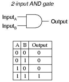
The “and” gate provides an output (a “1”) if both input A and input B are “1”, otherwise the output is “0”. That’s a simple binary statement.
The “exclusive or” is very important because it is actually the circuit that’s used to do arithmetic.
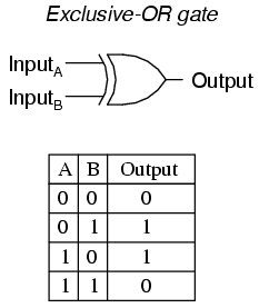
If we place a number of these gates in parallel we create an arithmetic unit, which is one of the most important parts of the computer. The following set of gates and add or subtract in binary:
This circuit adds two 4 bit words (a nibble). Here’s an example of how two 4-bit words (nibbles) are added together.
For homework you can try out some more examples. There will be a test on Friday (or not).
A Computer System
The basic architecture of a computer was defined in 1945 by physicist John von Neumann. It included all the basic elements that make up the computer. It is amazing to realize that this basic structure still defines the architecture of today’s computers. The computers have gotten smaller and more powerful, but still use the same architecture. The stored-program computer keeps its program instructions in memory, and processes them one at a time. The “control unit” and the “Arithmetic Logic Unit” are used to make sense out of each instruction.
The following diagram is a slightly modified architecture that provides more detail, and makes it easier to explain how the computer works.
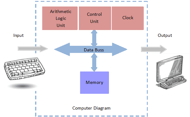
In the following explanation we assume a simplified computer based on the diagram above. The first computers used one byte (8 bits) at a time, but today’s computers can use eight bytes at a time (64 bits). Since it handles more data at the same time (in parallel) these computers are much faster.
Input Device
An input device can be a keyboard, network connection, USB, wireless connection, etc. It’s the place we input the instructions and the data that the computer will process. When you push one of the keys on the keyboard it is translated into binary code and then sent to the control unit. An IP camera has a computer that gets instructions from the network, and video from its sensors. These are all input processes. The IP door control reader has multiple inputs such as RFID reader, network data and input IO.
Memory
Back in 1963, when IBM introduced the 360 series of computers they referred to the memory of the computer as “storage” instead of “memory”. They did this because they were afraid that people would be worried about computers that had “memory”, which was a very human thing.
The memory in a general purpose computer is any component or device that can hold the binary data for a period of time. The memory holds the data and the instructions. The memory can be volatile, meaning that it can be lost (forgotten), when the power is off, or it can be permanent memory, that is remembered even when power is off. Random Access Memory (RAM) is volatile, while ROM (Read Only Memory), EPROM (Erasable Programmable Read Only Memory) or hard drives are permanent. The IP camera and the IP door control unit have a number of different types of memory, such as RAM, ROM, or EPROM.
Control Unit
The control unit contains logic gates that control the most basic operation of the computer. The control unit can also use machine code to step through hard-wired instructions that perform all the basic steps needed make the computer work. The microcode is usually stored in Read Only Memory (ROM). This is sometimes referred to as firmware or microcoding. This includes such operations as controlling the input, the output, fetching data or writing data to memory, and fetching instructions from memory. We use microcode to load the operating system into RAM. This is referred to as “bootstrapping”. It gets the computer going. Once the operating system is loaded the computer can provide all the typical resources that we see on our computer screen.
The IP camera and the IP door readers have very simple operating systems and are mostly controlled by the microcode.
Arithmetic Logic Unit
The arithmetic logic unit (ALU) does all the computations. This includes adding, subtracting, and even logic operations such as comparing one set of data to another. It does everything in binary. When the IP camera performs analytic functions it uses the ALU. For example it can compare one frame to another to determine if movement has occurred. The IP door reader compares the code that is read from the credential to a list of codes stored in its EPROM, so it can make a decision about opening the door.
Output
The output of the computer goes to the monitor, the network, USB port, printer, etc. It is the place the controller sends the result of all the processing that goes on inside the computer. For example, the IP camera sends encoded video out to the network. The IP door control unit provides a relay contact to open the door.
The Clock
The clock module is usually not shown in computer architecture drawings. It wasn’t present in the von Neumann architecture, but I think it is relevant to this discussion. The clock provides the basic timing for the computer. The clock speed determines how fast the instructions are processed. The clock speed is determined by how long it takes to get a process through the ALU, or store and fetch data from memory. It actually determines how fast the data moves across the “data bus”.
Coding and Programming
The computer doesn’t do anything unless it is programmed. The programmer creates step by step instructions that converts the computer into a processing device. There are a number of levels of computer coding or programming. There is firmware or microcode (which is the lowest level), the operating system, programming languages, and application programs (which are at the highest level).
The microcode creates machine language instructions that are used to create the operating system. An “assembler” is used to convert alpha instructions into binary. For example the “write” command is converted to 0000 0001 by the “assembler”. The instructions tell the computer exactly what do do. The instruction goes to the “controller” and creates a sequence of events such as move one byte of data from the input area to the ALU, fetch a byte from memory, add these two numbers, and place the result back in another location in memory. It’s all very detailed and intense.
The machine level instructions are also used to create higher level languages such as C++, Java, Python, etc. Using the higher level languages, the programmer creates applications such as order processing systems, web browsers, spread sheets, etc. They also create higher level applications that need to be programmed by the user, such as Excel or databases. So if you have used a spread sheet, you are actually doing coding. Welcome to the club.
Summary
Now you know everything, or at least enough to talk intelligently about a computer and what goes on inside the IP cameras, IP door controls, and other network attached security systems. Arthur C. Clark said, “Any sufficiently advanced technology is indistinguishable from magic.” Well, hopefully the computer is no longer “magic”.
If you need more information about any advanced technology, please contact us at 914-944-3425 or use our contact form.