How do you get the power from here to there?
A number of people have asked us about the gauge of wire required between a device and the power supply. They also want to know how far away these two devices can be. This article describes how to select the right wire and calculate the maximum length of the wire.
Your surveillance IP camera, electric door lock, an audio amplifier, or even an electric heater needs a certain voltage and current to operate. When the power is transmitted across a wire there is a voltage drop caused by the resistance of the wire. If the surveillance camera (the load) is 500 ft. away from the power supply (the source), and it requires 12 VDC, what type of wiring is required to assure that the device gets the right power?
You could always use a very thick wire (low gauge), but that can cost a lot more than thinner wire (high gauge). To calculate the right wire and length you first need to understand a few electrical engineering concepts and equations.
Electrical Engineering Formulas:
Don’t panic. This will be easy. The three most basic units in electricity are voltage (V), current (I), and resistance (r). Voltage is measured in volts, the current is measured in amps, and resistance is measured in ohms.

A neat analogy to help understand these terms is a water hose. The voltage is equivalent to the water pressure, the current is equivalent to the flow rate, and the resistance is like the hose size.
For example, if you are using your hose to water the lawn, you can spray the water further away by increasing the water pressure and consequently the flow rate of the water. There is a direct relationship between pressure, flow, and the hose diameter.
In a similar way, voltage, current, and resistance are related to each other by an electrical engineering formula called Ohm’s law.
V= I x R
Another important relationship defines electric power which is measured in watts. In an electrical system power (P) is equal to the voltage multiplied by the current.
P = VI
We can use this formula to calculate the current required by the load. If the camera requires 10 Watts (P) and it also uses 12 VDC, then the current can be calculated:
I = P/V
I= 10 watts / 12 V = 0.833 Amps
The Voltage Drop
Voltage drop is the reduction in voltage in an electrical circuit between the source and load. It is caused by current flowing through the wire which has some resistance.
The DC resistance of the conductor depends upon the conductor’s length, cross-sectional area, type of material, and temperature.
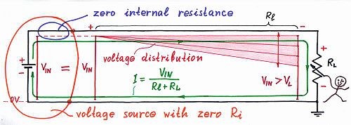
The local voltages along a long line decrease gradually from the source to the load.
If the voltage between the conductor and a fixed reference point is measured at many points along the conductor, the measured voltage will decrease gradually toward the load. As the current passes through a longer and longer conductor, more and more of the voltage is “lost” (unavailable to the load). This is due to the voltage drop developed across the resistance of the conductor. In the diagram above the voltage drop along the conductor is represented by the shaded area. The local voltages along the line decrease gradually from the source to the load. If the load current increases, the voltage drop in the supply conductor also increases. Voltage drop exists in both supply and return wires of a circuit.
We can calculate the voltage at the load when we know the power used by the device and the source voltage. Take a look at the following diagram. This is a simplification of the total system that includes the resistance of the wire, the load, and the source.
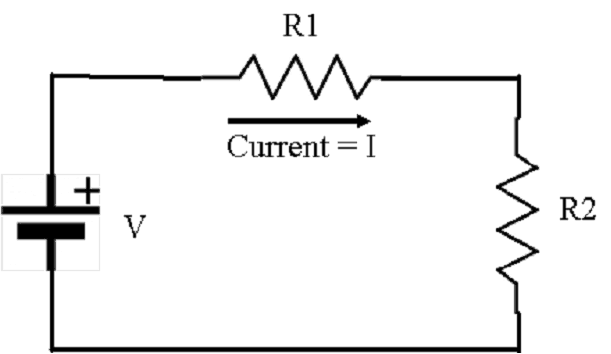
R1 is the resistance of the wire. R2 is the resistance of the load. V is the Source voltage. You can calculate the voltage drop at the end of the wire if you know the resistance of the wire and the current expected.
The value of R1 can be found in a table that lists the resistance per foot (or meter) for specific gauge wire. You can find these tables on the web. For example, look at http://www.bulkwire.com/wireresistance.asp. This chart is for DC (direct current). The values are slightly different for AC (alternating current), so make sure you use the right chart for your calculations.
An Example of the Calculation
Now let’s do a sample calculation. Let’s use the camera that requires 12 VDC and uses 10 watts. We determined that it requires 0.833 amps. Using Ohm’s law we can calculate the resistance of a camera.
R = V / I
R = 12 VDC / 0.833 amps = 14.4 ohms.
So this means R2 in our diagram equals 14.4 ohms.
Next, let’s use the table to determine the resistance of the wire. Let’s assume that we have a wire run of 500 ft. and we decide to use 18 gauge wire. Looking at the chart the wire has a drop of 6.5227 per 1000 ft. Since we only want to go 500 ft. we get:
R1 = 6.5227 / 2 = 3.26 ohms
Now we can determine the voltage at the load R2. To do this we calculate the current through the circuit:
I = V / (R1 +R2) = 12 / (3.26 +14.4) = 0.68 amps
Finally, we calculate the voltage across the load (the camera). Note many cameras will operate at 10% less than the nominal voltage. So if we have a camera that requires a nominal 12 VDC, it will operate correctly if the voltage is 10.8 volts.
V2 = 0.68 x 14.4 = 9.79 volts.
Uh oh, we’re in trouble! Since the calculated voltage is lower than 90% of 12 V (10.8V), this camera will not work. We need to do something to increase the voltage at the camera. We can either increase the source voltage or change the wire gauge so it doesn’t cause so much voltage drop.
Let’s go back to the table and see if we can adjust the wire gauge. If we use 12 gauge wire, the resistance drop is 1.19 ohms (2.37 / 2). The total current is then:
I = 12 / 15.59 ohms = 0.77 amps.
And then the voltage across the camera is 0.77 x 14.4 = 11.08 Volts.
That will work.
We can also calculate the allowable wire resistance since we know the current we need. Once we know the resistance, we can use the chart to select the right wire gauge. I don’t want to get too complicated so we will leave this calculation to a future article.
Power over Ethernet (PoE)
What about devices that use Power over Ethernet (PoE)? Do you need to worry about the wire and the length? Actually, you don’t need to worry about this. Devices that use PoE are a lot simpler to deal with. You don’t need to deal with the cable since it uses the standard Ethernet wiring. You just have to make sure the PoE midspan or injector provides enough power for the device. The wire length is controlled by the maximum Ethernet network cable run which is 100 M (328 ft.). The network cable type is 22 gauge. There will be a voltage drop from the source (the network switch or midspan), but it is all handled by the PoE design.
PoE power sources provide more than the nominal 48 volts specified to allow for the voltage drop. Higher power PoE midspans or injectors provide higher source voltage. And the powered devices (load) are designed to support a much wider voltage range so they will operate at plus or minus 20% V or more.
Summary
IP cameras and other security systems won’t work correctly unless they have the right power. The gauge of the power wiring is key to installing a working system. By using Ohm’s law you can calculate exactly the right size wire.
So that’s how we do it. If you need help determining the right cable please contact us. We have a lot of experience with the total security system, so I’m sure we can be helpful. We can be reached at 914-944-3425 or 1-800-431-1658 (in the USA) or just use our contact form.