PoE makes installation very easy
By Bob Mesnik
This article has been updated on 10/4/2018 to reflect the new PoE injectors available.
Many network-attached devices, such as IP cameras, VoIP phones, WiFi radios, and IP door readers use power over Ethernet (PoE). The single network cable transfers both data and power to the device making installation very simple. The data uses one set of wires, while the power uses another set of wires in the network cable.
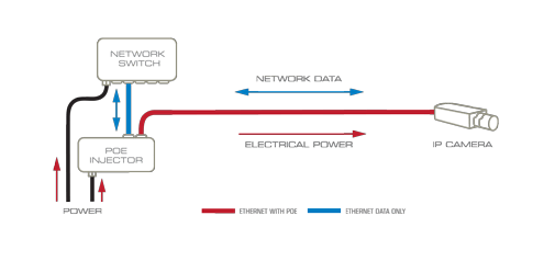
Power over Ethernet is one of the things that make installation of IP camera systems very easy.
The device that inserts power onto certain pairs of wires in the Ethernet cable is called an “injector” or “midspan”. Power is injected onto the Ethernet cable using a separate power source (injector) or using a network switch that includes built-in PoE. Many devices, that use PoE, conform to the IEEE standard. But be careful, there are some devices that don’t conform to this standard. It’s important to know exactly what voltage and current the device needs before using PoE. Here is a review of the technology.
Standards Used for Power Over Ethernet
IEEE 802.3 is the standard that defines the physical layer for Ethernet cabling. It includes the type of wire, the signal levels, and the bandwidth. In 2003 the standard was updated to include PoE. IEEE 802.3af defined the voltage and power available power for devices on the network. This specification provided PoE that provided up to 15.4 watts. The specification was updated again in 2009. IEEE 802.3at provided higher powered (25.5 watts) which is referred to as PoE+.
PoE injectors that conform to IEEE standard provide between 44 and 57 volts. The effective distance of cable is the same as the standard Ethernet distance of 100 m (328 ft.). There are two modes, A and B, for powering the devices. The modes define the wires pairs and polarity of the voltage used for power. New PoE injectors can provide over 50 watts of power to the network attached device. These higher power over Ethernet devices use two pairs of wires to carry the power to the device.
PoE Injector Technology:
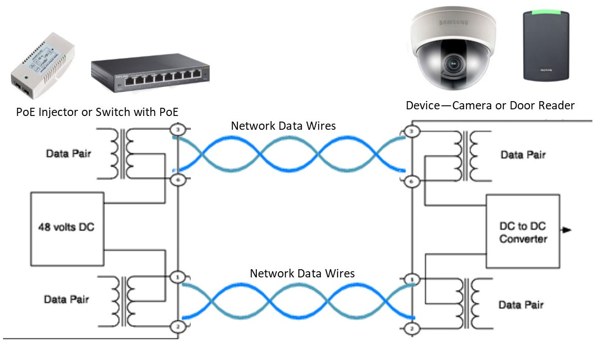
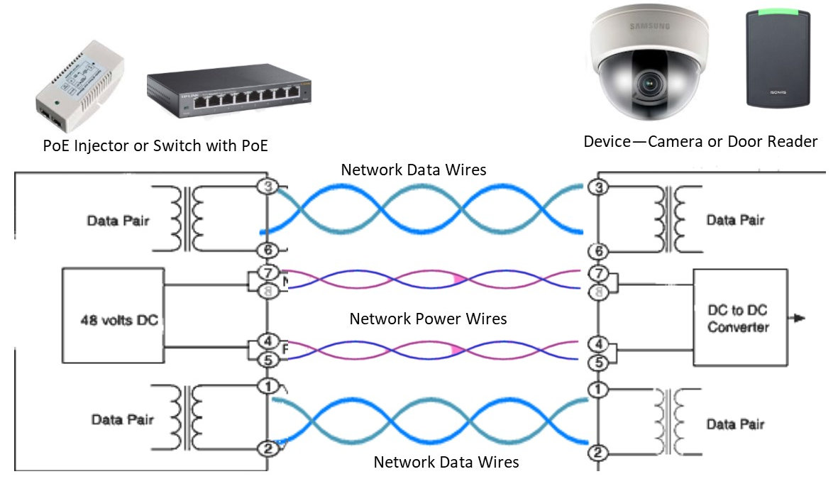
In all cases, power is sent over the network wires. In the mode A configuration, the power is provided on the same wires as the signal. In the mode B configuration, the power is provided over two alternative sets of wires in the network cable.
The diagram below shows Mode A configuration. The power is provided by a network switch that includes PoE on the ports or by an injector that connects between the switch and the device.
The following diagram shows the Mode B configuration. In this case, the power from the switch or the injector is provided on separate network wires. Many devices are designed to accept power using a mode A or mode B configuration.
The wires are a quite narrow gauge (24-gauge) so cable resistance reduces the power available at the device and depends on the distance from the source. Take a look at our article, Calculating the Wire Gauge for Power to Your Device, to learn more about voltage drop. The standard defines the nominal PoE voltage at 48 volts. The voltage level at the injector is designed to be about 57 volts but is then reduced by the resistance in the wire to about 44 volts by the time it gets to a distant device. There are various injectors available that can provide more power to the device. This means they have a higher current capability and thus provide more power at 48 volts.
There are some passive PoE sources and there are “active” or “smart” type sources. The “active” type communicate with the device. This provides device protection that can prevent damage caused by short circuits, as well as providing overcurrent and overvoltage protection. The passive PoE sources are less expensive and provide power without any verification from the device.
Power sources that conform to the IEE standard include network switches individual or multiport PoE injectors (or midspans).
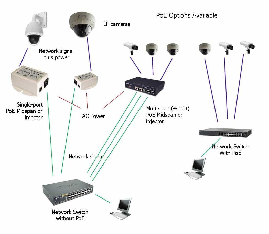
Power Source Using a Network Switch that includes PoE
There are a number of network switches that include PoE source on some or all their ports. Even though many switches will say they provide power, they can be quite different in capability. Most of these switches will provide 15.5 or 25.2 watts (PoE+) on the PoE port. Some switches include power on some of their ports and not others. You have to be careful about which port you use for the PoE device.
Some switches have PoE on all the ports but have a power budget that limits the total power available to the connected devices. For example, if an 8-port switch has a power budget of 32 watts, it can actually support only 2 devices that use 15.5 watts each.
Power sources using a Mid-span or Power injector
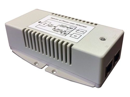
Power injectors are available as a single device or multi-port units. Multi-port injectors are available from a number of manufacturers and support standard PoE or PoE+ power to multiple devices. They are available with 4-port, 8-port, 16-port, and even 24-port configurations. Since these devices also pass the data on the network, make sure you select an injector that meets your network speed. They are available in 100 Megabit or Gigabit bandwidth.
Single device injectors are available with much higher power levels. These very high power units can provide up to 100 watts, using 4 wires in the network cable. This higher power level allows you to power some of the PTZ type cameras that require much higher power levels. Always check that the PoE source is compatible with the camera.
If you still have questions about PoE or need help selecting the right PoE for a specific IP camera system, just call us at 1-800-431-1658 in the USA, or 914-944-3425 everywhere else, or use our contact form.